Dual Powered Standard PCB3B Willem EPROM Programmer
User Guide
Main Board / Cables
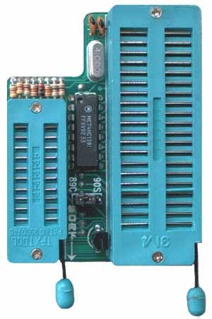
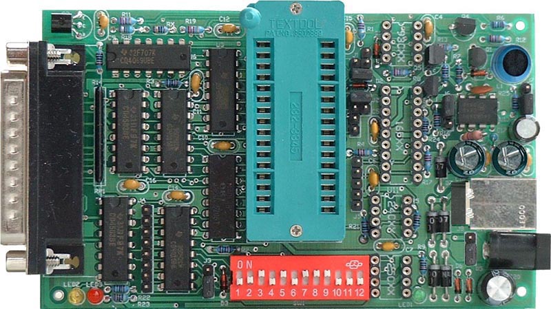
Main Board
|
Parallel Data Cable (Printer extension cable, with male-female 25 pin connector, and pin to pin through) |
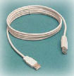
A-A type USB cable(for power) |
|
|
|
Optional Items:
|
ATMEL 89 Adapter |
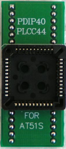
ATMEL PLCC 44 Adapter |
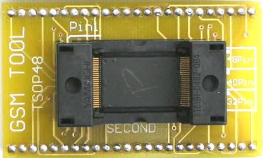
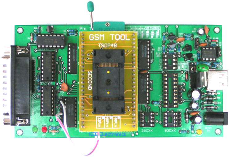
TSOP 48 Adapter |
|
|
|
|
|
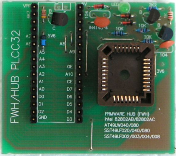
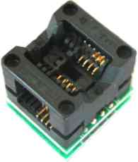
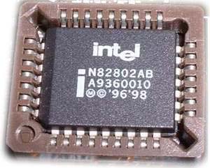
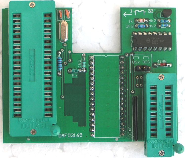
FWH/HUB PLCC32Adapter |
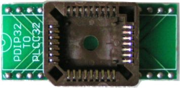
PLCC32 Adapter |
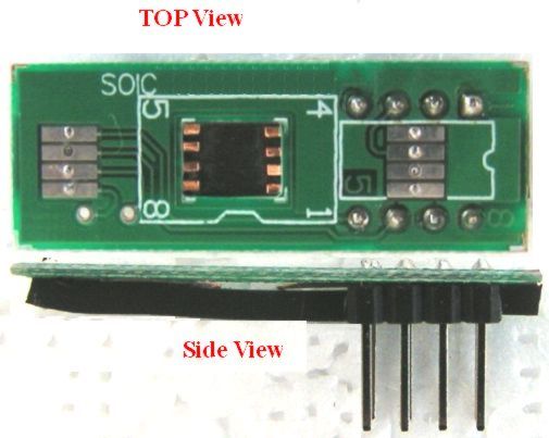
SOIC Adapter(Simplified) |
|
|
|
|
|
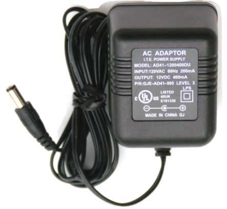
AC or DC Power Adapter (9V or 12V, 200mA) |
SOIC Adapter(Professional) |
|
|
|
|
|
Hardware Installation & Configuration
|
| |||
|
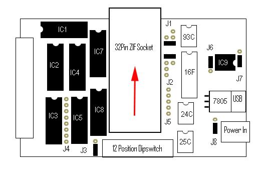
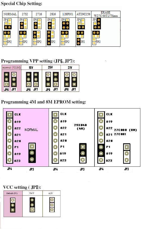
Hardware Layout | |||
|
| |||
|
|
|
| |
|
|
| ||
|
|
| ||
|
|
| ||
|
|
|
|
|
|
| |||
|
Installation Steps
(Note: the LPT port of PC MUST set to ECP or ECP+EPP during BIOS setup. To enter the BIOS setting mode, you need press "Del" key or "F1" key during the computer selftest, which is the moment of computer just power up.)
Software Operation | |||
| |||
|
| |||
|
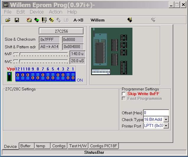
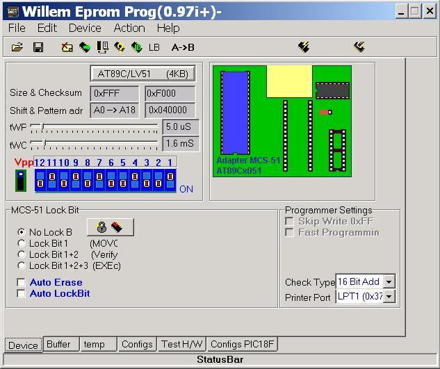
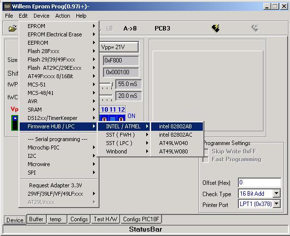
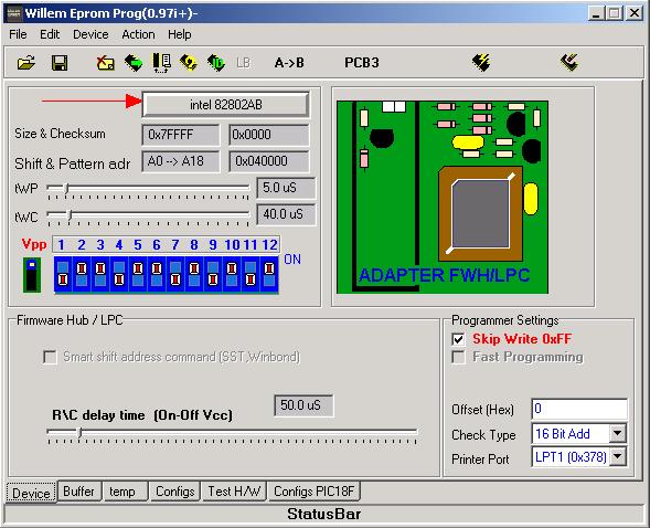
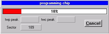
The software interface:
| |||
|
| |||
|
Hardware
Check
| |||
|
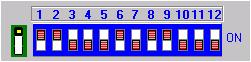
Note: the Vcc setting jumper only has effect when you are using AC adaptor as power source. For the USB power only 5V Vcc is available. DIP Switch
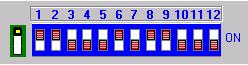
When programming one chip, follow the program prompt to set DIP switch .
| |||
|
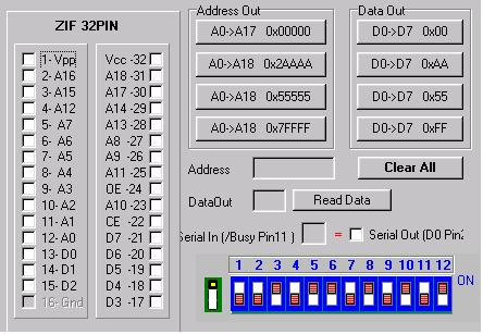
The screen : | ||||||||||||||||||||||||||||||||||||||||||||||||||||||||||||||||||||||||||||||||||||||||||||||||||||||||||||||||||||||||||||||||||
|
| ||||||||||||||||||||||||||||||||||||||||||||||||||||||||||||||||||||||||||||||||||||||||||||||||||||||||||||||||||||||||||||||||||
|
Steps:
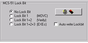
This adaptor is able to program MCS-51 series PLCC MCU, such as 89C51PLCC44. Please note, it is used with ATMEL89 Adapor.
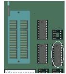
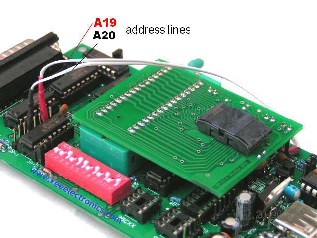
This adaptor is able to program TSOP48 flash chip. More details please see supported device list. The default jumper setting on the base board is above. Please change it as needed. JP2 jumper keep it close normorlly. It will increase the compatibility betwwen the similar device . Only try to open it for some chip if programming fail. The JP2 jumper is not in the original design and it also not documented for the most of chip. Bellow is the TSOP48 adaptor on board, please reffer to jumper setting section for A19 and A20 connection:
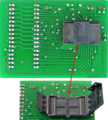
TSOP48-S adaptor TSOP48-S adaptor, which is replacement of TSOP48 adaptor with 100% compatibility. Cost for value some more.
TSOP48-S adaptor on board
| ||||||||||||||||||||||||||||||||||||||||||||||||||||||||||||||||||||||||||||||||||||||||||||||||||||||||||||||||||||||||||||||||||